Intro
In this mini-series I will go through the process of creating a rig that can turn a quadruped walk into left and right turns interactively, using the power of blender drivers!
Part I: Getting it to work!
In part 1 I will clarify on why exactly having this kind of rig setup can be useful. I will give a brief overview and introduction to the math concepts used. And finally, I will elaborate on what exactly drivers are, and why they are so powerful.
note: I am using blender drivers for this, but this approach should be transferable to most DCC applications with comprehensive rigging/animation tools
What problem are we trying to solve?
Animating a quadruped comes with its own obstacles. Our project revolves around a quadruped moving about in Augmented Reality, and is driven by root motion. Creating animal gaits is not a trivial task, and can be time-consuming. Even more so if the workflow doesn’t lend itself useful for an iterative process. Only having to deal with the animal’s forward motion is great if you have to jump back and fourth in your process, as we did. Imagine being able to put a lot of personality into the various gaits you need to animate, and have it seamlessly translate into the left and right versions.
On a more technical note, when driven by root motion, how much and how fast does your animal turn? These are questions automatically handled in our proposed solution.
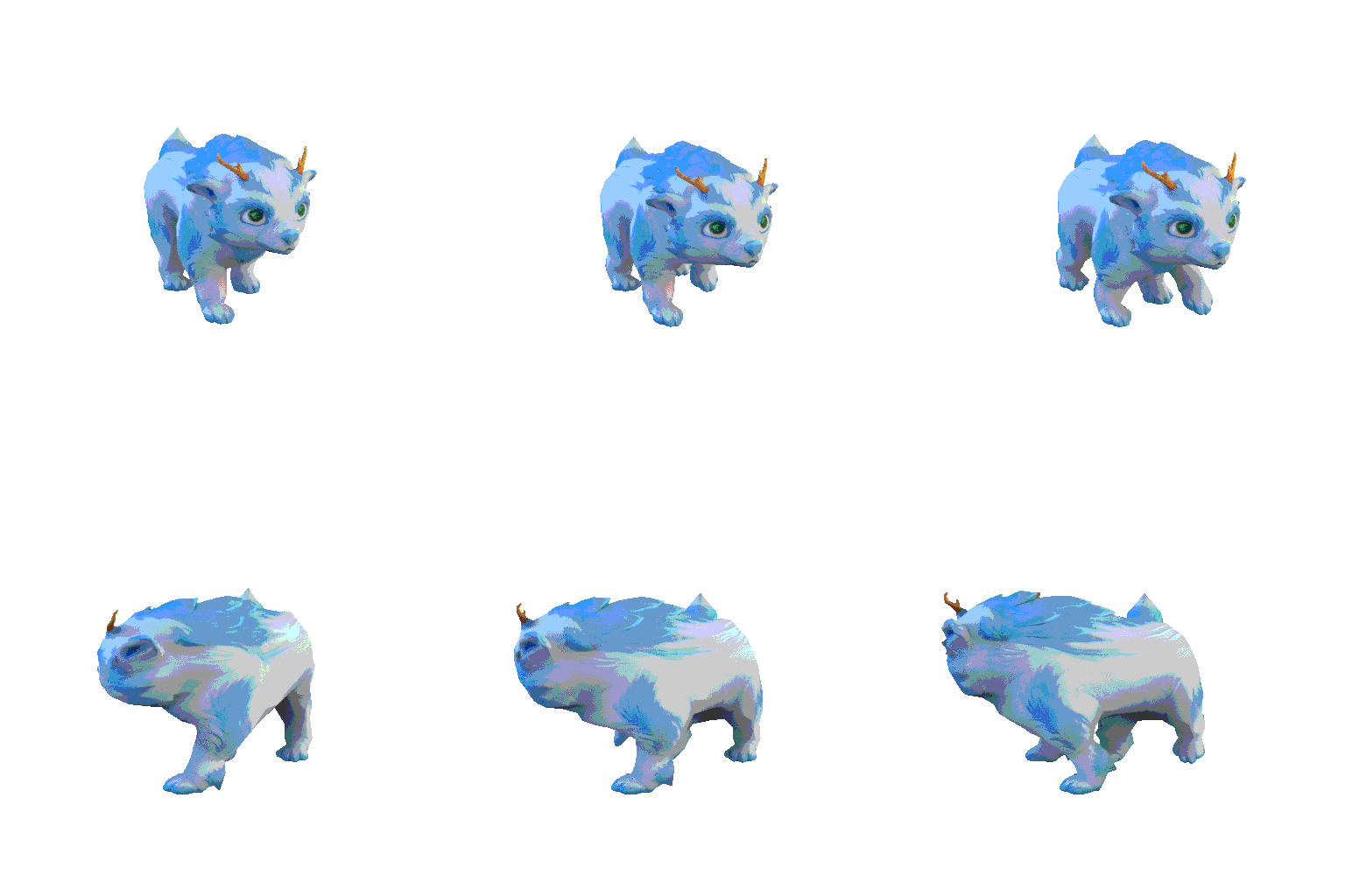
In our solution, essentially we just define a circle, or arc, that the quadruped walks along. We have a single control, which is the radius of this circle. It goes into minus to define whether the turn is left or right. This is a useful control to interactively change, as we get a live preview of various degrees of rotation. Depending on whether you’re animating a walk or a gallop, this can end up looking weird, or ideal.
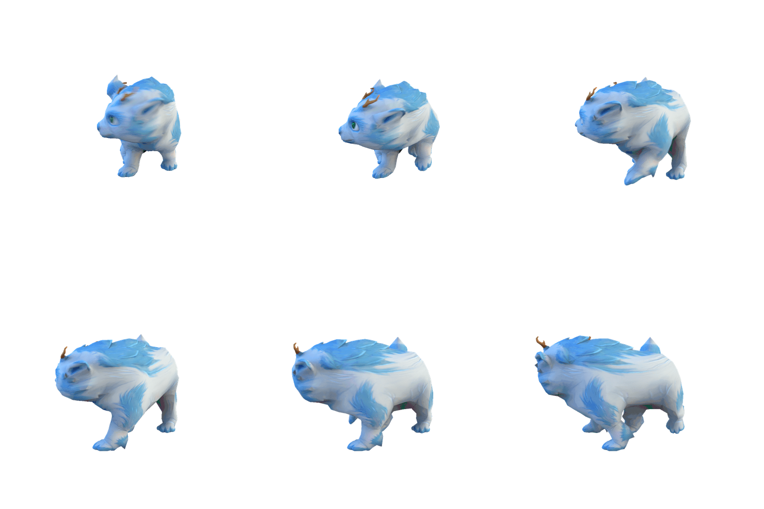
The interactive control and live preview is really the strength of drivers, and what I’m going to introduce in this post.
Using blender drivers and math to solve it!
I will try to be as clear as possible, but also concise, as I am not planning on going in-depth with the math concepts used. There is a plethora of information on the interwebs for that!
The Math
The quadruped is a complex problem, but really just a collection of simple problems. So starting simple, what we initially want to solve is to take the forward motion of the animal’s root bone, and translate that into an arc, or ‘radians on a circle’.
The main concept used has to do with Arcs. More specifically Arc Length. Arc Length is expressed as:
Where s defines the length, r is the radius and $\theta$ our angle. In the problem we are trying to solve, we already have the length s, as this is how far the animal has travelled forward. We also want to be able to change our radius, so what we are solving for is our angle $\theta$, which gives us this equation:
Also known as the radian measure. As we are dealing with radian degrees, and not angle degrees. A good example to visualise this, is to use a unit circle. This just means a circle where the radius equals 1. In our example, we can say that it’s 1m. When the animal travels 1m forward, it also travels 1m on the circle. That’s why the unit circle makes a good simple case.
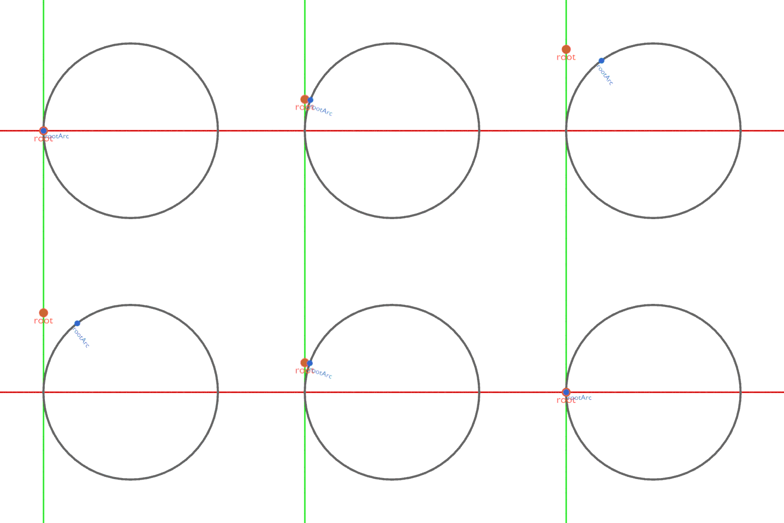
If root is the bone we translate, rootArc is the bone that is driven, which means we need to tell it what to drive by. With a radius of 1m, this is as simple as putting the root’s forward position in cosine(x) and sine(y).
Which produces this example:
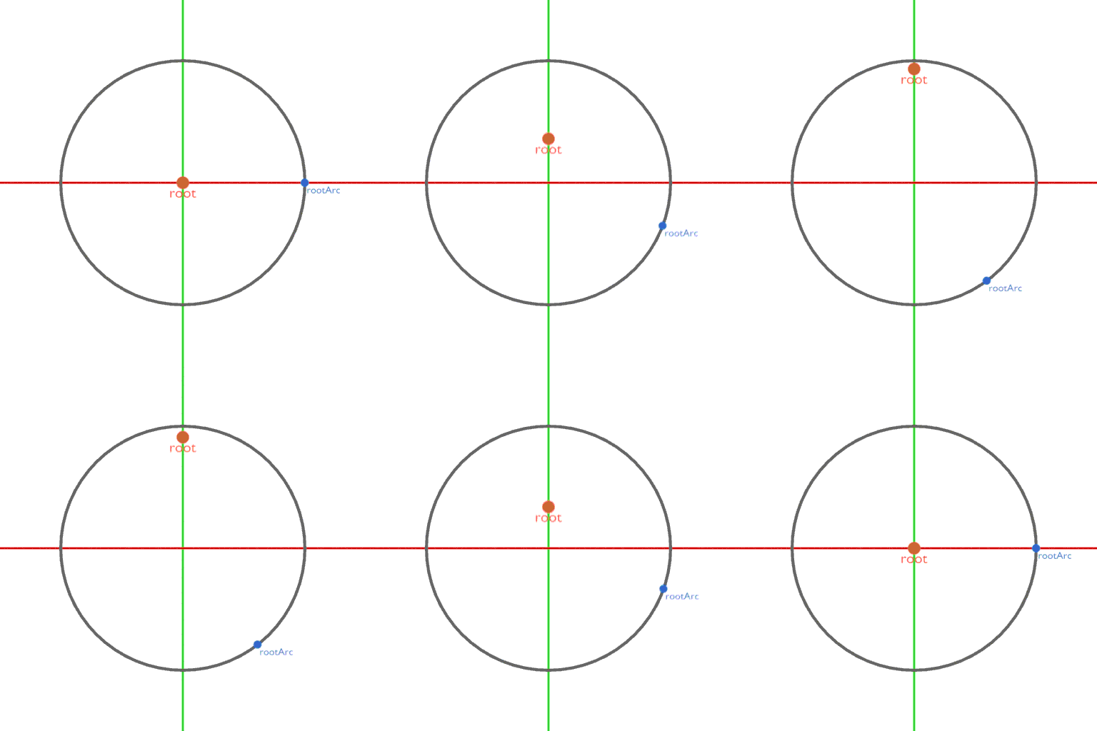
This certainly has some effect, but what you might notice is that rootArc is not moving from the correct position, or in the correct direction. To get this right, we need to do a bit of offsetting. We offset by adding the radius on the x-axis, and inversing our equations.
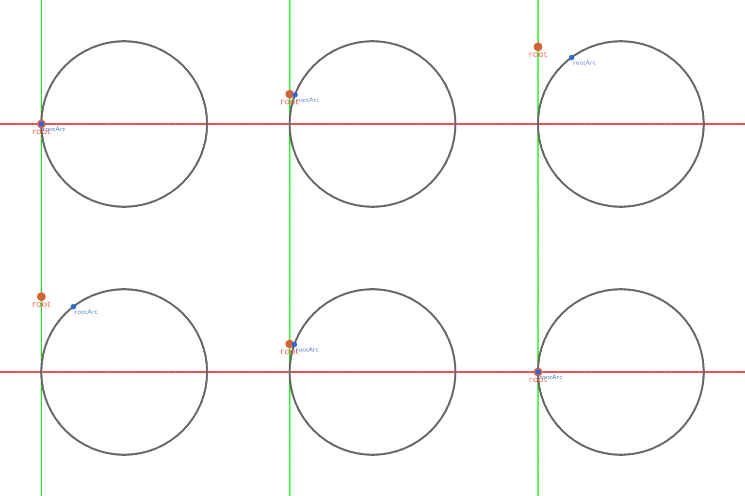
Before we have a viable solution, we need to address the orientation of our rootArc. The orientation is the distance travelled over the inverse of the radius.
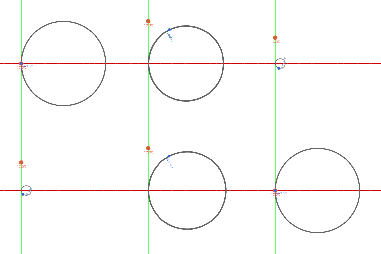
This piece gives us the last piece of an almost viable solution. However, we would like to add an additional feature, which is interactively changing the radius of the circle. Instead of adding the radius, we subtract the inverse of the radius. This is so it will work regardless whether the radius is minus or not, and will change left/right depending on it. Other than that, instead of simply taking the cosine and sine of root, we divide root by radius first, to shrink down the distance travelled. To change the size of our circle, we lastly multiply by the radius.
And then we are left with the final result, where we can interactively change the radius, and the driven properties of rootArc will adapt.
The driver setup in Blender
Drivers at the base level is the idea of x driving y. In other words, the position of x becomes the rotation of y. I like to see drivers fit in a stairwell of rigging complexity.
- Step 1: Child/Parent hierarchy
- This is the most basic rigging needed. The idea of creating a hierarchy where any bone that is child of a parent, will inherit the parents transformations.
- Step 2: Constraints
- Constraints help a great deal when creating a control rig, and quickly getting the correct behaviour from a rig. Sometimes we want the children to take control, or simply have the body behave in a more flexible way than a simple hierarchy.
- Step 3: Drivers
- Drivers can be both simple and complex, which is really what makes them very powerful. A simple driver could be to drive a bone’s x position by another bone’s y position. This same effect could be achieved through constraints, but with drivers, because we can work with script expressions, we could do something like this instead: boneA_x = boneB_y * 2
The expressions used to drive bones or objects are really only limited by your understanding of math. If drivers still seem a bit foggy, try to drive some primitives by others yourself, and play around with moving them to see how it works.
To set up a workable rig we need 3 bones; root, rootArc and radius. Both root and rootArc should be placed in word zero. Put the radius bone one unit in the positive X direction. Depending on the orientation of your bones, the exact axes to use might vary. I will assume an XY plane and Z rotation(XYZ Euler).
Add drivers to these three values on the rootArc bone. Now we can populate the expression field with the theory from the earlier section. First we gather our variables of which we only have two; root’s Y position in world, and radius’ bone’s X position in world. Add these for all three drivers, in the Driver tab.
Lastly, populate the three drivers with each their expression:
x = r*-cos(root/r)-(-r)

y = r*-sin(root/r)

zRot = root/-r
Essentially, we just programmed our own rigging behaviour!
This is the end of Part I. I hope it gave some insights into the fundamental idea of our rig, as well as helped introduce some knowledge about drivers and more advanced rigging concepts.


